Free Download Altair PollEx 2024.0 with PDF Documentation | 784.8 mb
Altairhas releasedPollEx 2024.0is a PCB-level Electronic Design Automation (EDA) software suite covering design review, analysis and manufacturing
Owner:Altair
Product Name:PollEx
Version:2024.0 with PDF Documentation
Supported Architectures:x64
Website Home Page :www.altair.com
Languages Supported:multilanguage
System Requirements:Windows *
Size:784.8 mb
.
Altair PollEx 2024.0 Release Notes
Highlights
– Added a new checking item of Rigid-Flex PCB in the FPCB category of DFM to check the design rules in the Flexible area such as PCB Outline radius, solid copper plane, and Reinforcing copper.
– Added a feature to import the UPF libraries from Ultra Librarian in the Parts dialog of PollEx PCB.
– Added a cross-probe feature in Technical Cleanliness between hazardous analysis results in PCB and the ECAD tool.
– Added the Electrical Conductor Spacing item in DFE. When conducting spacing checks between two nets, it is now possible to specify an appropriate spacing value based on the voltage difference between the two nets. Additionally, spacing checks can be performed with different spacing values depending on the solder mask open status of the nets. Using this item, we can check whether there is a possibility of sparks occurring between nets.
– Enhanced the Zuken CR-8000/CR-5000 importer to support the Solder Resist layer, and to recognize the sub-mesh of the copper polygon shapes.
PollEx Modeler
PCB
– Added a feature to import the UPF libraries from Ultra Librarian in the Parts dialog of PollEx
PCB
PollEx Verification
DFM
– Added a new checking item of Rigid-Flex PCB in the FPCB category of DFM to check the design rules in the Flexible area such as PCB Outline radius, solid copper plane, and Reinforcing copper.
DFE
– Added the Electrical Conductor Spacing item in DFE. When conducting spacing checks between two nets, it is now possible to specify an appropriate spacing value based on the voltage difference between the two nets. Additionally, spacing checks can be performed with different spacing values depending on the solder mask open status of the nets. Using this item, we can check whether there is a possibility of sparks occurring between nets.
PollEx Modeler
PCB
– Added the Number of Pins and Net Length Status attributes in the Net Length Viewer dialog. CP (CrossProbe)
– Added a warning message when comparing different data formats (i.e., Altium Designer and ODB++). ECAD Interface
– Enhanced the Cadence Allegro Importer to recognize the default Board Outline Layer Name as DESIGN_OUTLINE.
– Enhanced the Cadence Allegro importer to distinguish between the default and subclass layers.
– Enhanced the Zuken CR-8000/CR-5000 importer to support the Solder Resist layer.
– Enhanced the Zuken CR-8000/CR-5000 importer to recognize the sub-mesh of the copper polygon shapes.
– Enhanced text spacing in Siemens Xpedition importer.
– Enhanced the layer setup in Siemens Xpedition Binary importer to recognize CONTOUR objects as the Hole.
– Enhanced the Siemens Xpedition Binary importer to import the Generated Silkscreen layers.
– Changed the Copper Layer Name format to SIGNAL_# for Siemens Xpedition ASCII importer to match with the original Xpedition data layer name.
PollEx Verification
DFM
– Added an option in the Under Hole/Via item to check if the slit hole exists in the specific component area.
– Added an option in the Hole Distance item to check Solder Mask Annular ring size of the NPTH.
– Added an option in the Conformal Coating item to check the minimum count of NPTH by the hole size in a specific component area.
– Added an option in the Under Hole/Via item to define the target objects using Padstack String Filter.
– Added an option in the Hole Through Pad item to check "Except Via in Pad Area" by classifying SMD and NSMD pads.
– Added an option in the Under Hole/Via item to expand the area of the target component.
– Added an option in the Placement Mark item to check the alignment of the placement mark between two components.
– Added an option in the Min Width item to check all the segments in target Nets.
– Added an option in the Min Width item to check the bottleneck of the route pattern.
– Added an option in the Min Width item to check the minimum width of the Line and Arc objects separately on the route patterns.
– Added an option in the Min Width item to allow shorter route patterns than the length limit.
– Added an option in the Via S/R Spacing item to check the clearance between via solder mask and figure solder mask.
– Added an option in the Component Placement Angle item to check the component placement angle based on the SMT soldering direction.
– Added an option in the Guide Hole item to define the guide holes using Padstack String Filter.
– Enhanced the PCB Outline Measure Base option in the PCB Outline Spacing item.
– Added an option in the Acute Angle item to exclude route pattern segments connected to the copper plane.
– Added an option in the Lines Between Two Pins item to exclude copper planes from the target objects.
– Added an option in the Dip Annular Ring item to check the existence of non-functional pads on the inner layer.
– Added an option in the Via Annular Ring item to check the existence of non-functional pads on the inner layer.
– Added an option in the Jig Hole item to check specific hole existence on the center of the PCB Board.
– Added an option in the Solder Resist Pad item to check the distance between Pad and Solder Mask by classifying SMD and NSMD pads.
– Enhanced the Test Point 2 item result to include the layer information.
– Added an option in the Bending Area item to check maintained straight patterns within the transition area.
– Enhanced the Layer Definition in the Min Same Net Spacing and Width item.
– Added an option in the Via Annular Ring item to define the target Via types.
– Added an option in the Unrouted Net item to separate Pattern Connection check.
DFE
– Added a Net of Comp option in Component to Net Clearance tem, to check the distance between components connected to a specific net and surrounding vias.
– Added a Detour Length option in Keep off pair Comp item, to check the detour length of holes if the hole exist between components during the spacing check between components.
– Added a Count Type and Count option in Component Position item to check the min/max/ range count of components.
– Added a Measure Base option in 3D Clearance item for users to set measurement criteria when measuring spacing distances between components.
– Enhanced a feature in Composite Net Filter dialog, to prevent user errors, changed the default condition during Composite Net configuration so that the Ground Net is excluded by default.
– Enhanced a feature in Complete Shield, Diff-Complete Shield and Net Group Shield items, the issue where test options were applied differently during Shield check, ensuring apply same options across all items.
– Enhance a feature in Input dialog so that when changing the Functional Type in the Properties/Parts Dialog, the Local UPF’s Part Classification is automatically updated to reflect the same content.
DFE+
– Added a Strobe to Strobe Skew check type in Timing Skew item to check timing skew between differential pairs.
– Added a Net Combination option in Timing Skew item. During Strobed Bus Skew check, a Net Combination option has been added to allow setting relationships between the strobe net and dependent nets.
– Added a Delay Time check type in Flight Time item to check the delay time of transmission lines using the results of Transmission Line Analysis.
– Enhanced a feature in Timing Skew item. During timing skew checks, when there are multiple load components, the skew between the driver and each load component is now individually checked.
– Enhance a feature in Flight Time item. Currently, only the flight time of the positive net is checked for a differential pair net. However, it has been improved to check the flight time of both the positive and negative nets.
– Enhanced a feature in Flight Time, Timing Margin and Timing Skew items, during buffer model setup, for differential pairs, the menu has been modified to allow setting up buffers for both the Positive and Negative pins separately.
Technical Cleanliness
– Added a cross-probe feature between hazardous analysis results in PCB and the ECAD tool.
– Added a feature to create a log file.
– Added a Notification Message displayed when the Unit notation of the Design is not a millimeter unit.
– Enhanced the Hazard area shapes between two rounded rectangle pads in the analysis results.
– Enhanced the performance speed of analysis and result reports.
– Enhanced the result report. This added feature of the Formatted Outline displays specified results from the analysis summary sheet in the report for easy data transfer.
PollEx Solver
SI
– Added an Assign Pin Paring Information menu button in the Parts dialog. This menu automatically pairs pins connected to nets with a Net Type set to Diff Pair even when an IBIS model is not connected.
– Added a Use Simple Models option in the Network Analysis feature to perform analysis without using buffer models, instead utilizing voltage sources and terminations as driver/ receiver models.
– Enhanced a feature in the Net Topology Analyzer to allow Net Topology creation for objects with many nodes, such as ground.
– Enhanced a feature in Network Analysis to automatically adjust the simulation time to an appropriate value when changing the operating frequency during the waveform analysis.
PI
– Enhanced a feature in the Select Power Net Pins dialog to allow setting Source/Load pins in the same section.
– Enhanced a feature in the IR-Drop analysis to make the IR-Drop result screen resizable.
– Fixed a bug that some STEP-REPEAT information is missing in the ODB++ importer of PCB.
– Fixed bugs of Simens Xpedition Binary importer such as missing Fiducial Mark, wrong Component Height Value, missing Placement Obstruct objects from the Keepout Layer, missing Copper shape in the Dummy Pad, missing Cell Properties, and missing Fiducial Mark.
LDFE
– Fixed a bug in Stress Test Capacitor item if pin numbers were not assigned to the capacitor.
DFE
– Fixed a bug in Differential Pair Net item to generate correctly fill-cut areas for components placed at certain angles.
– Fixed a bug in Differential Pair Net item where the pass results of the Fill-Cut check were not being recorded.
– Fixed a bug in Component to Net Clearance item where layer numbers were not displayed in the Result data.
– Fixed a bug in Net to Net item of incorrectly checking the distance between traces and polygons.
– Resolve an issue in Length item. When checking the length of a Composite Net, it checks the full length from the Start Component to the End Component.
DFE+
– Fixed a bug in Timing Skew check item that the Result Table’s values did not match the measured values in the waveform.
– Fixed a bug in Input dialog when executing the Define Differential Net Pairs menu.
– Fixed a bug in Impedance Check item where the PIN/VIA Escape option was not being applied during testing.
– Fixed a bug in Impedance Check item where the tool was unable to recognize the name when using a Material Name consisting only of numbers.
SI
– Fixed a bug in the Composite Net feature where pin mapping for multi-pin components was not created correctly when UPF was not used.
– Fixed a bug in the Data Line Analysis feature where analyzing in Periodic mode resulted in incorrect timing measurements in the waveform.
– Fixed a bug in the Net Topology Analyzer where the eye-diagram appeared abnormally when analyzing Differential Pair Nets, with different voltage swings between the Positive and Negative nets.
– Fixed a bug in the Waveform Viewer window of incorrectly generating Vdiff eye-diagrams when there are different voltage swings between the Positive and Negative nets in the analysis results of Differential Pair Nets.
– Fixed a bug in the Layer Stackup window where the VIA shapes disappeared from the right- hand side layer stackup diagram when executing the Apply button menu.
– Fixed a bug in the Network Analysis feature where AC termination was not being applied in the analysis of the Differential Pair Net structure.
– Fixed a bug in the Net Topology Analyzer feature where the net topology was incorrectly generated for a differential pair net with a feedback line.
– Resolved an issue in ADD/CMD/CTRL Line Analysis feature that only components capable of acting as drivers are listed when setting the Active Driver.
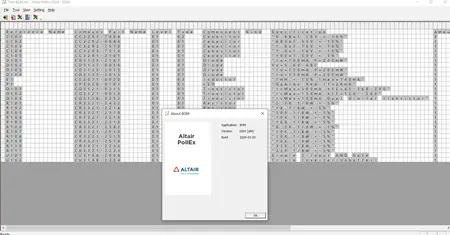
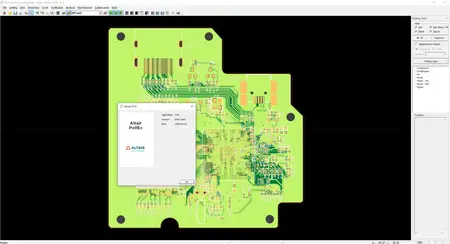
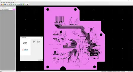
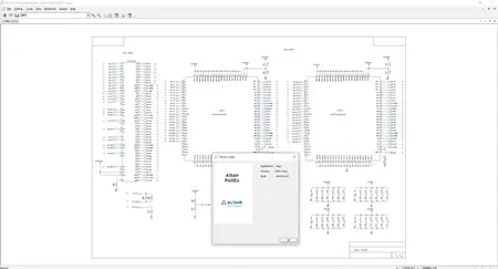
PollExis the most comprehensive and integrated set of PCB design viewing, analysis and verification tools. It provides powerful rule-based checking tools (DFM, DFA and DFE) to detect faults early in design and also provides easy solution for SI and thermal analysis of PCBs using the integrated parts and material libraries. PollEx is not just a printed circuit board (PCB) verification tool, it is solution that accelerates the development of today’s smart, connected, and tightly packaged electronic products. It is used by global industry leaders to improve efficiency, increase performance, enable teamwork, and enhance collaboration. Altair offers tools for full system analysis that integrate mechanical, thermal, electromagnetic, and embedded code design flow with PCB design.
Altair PollEx – Advanced Capabilities Overview
Altair PollEx is the most comprehensive and integrated set of PCB design review and verification tools in the market for electrical, electronics and manufacturing engineers. PollEx Advanced Tools includes PollEx PCB Verification (DFM, DFA, DFE, DFE+ and Logic DFE), Solver (SI, PI and Thermal), MFGs (Mounting Emulator, Metal Mask Manager, Soldering Amount Calculator and etc.) and PollEx PCB UPE (Unified Part Editor).
Altairis a global technology company that provides software and cloud solutions in the areas of product development, high performance computing (HPC) and data analytics. Altair enables organizations across broad industry segments to compete more effectively in a connected world while creating a more sustainable future.


Leave a Reply
You must be logged in to post a comment.