Free Download ANSYS Zemax OpticStudio 2024 R1.00 | 1.8 Gb
Zemax, a part of the Ansys family, has released OpticStudio 2024 R1.00 is the standard for optical, illumination, and laser system design in universities around the world, and in leading companies throughout the optics industry.
Owner:ANSYS
Product Name:Zemax OpticStudio
Version:2024 R1.00
Supported Architectures:x64
Website Home Page :www.zemax.com/www.ansys.com
Languages Supported:english
System Requirements:Windows *
Size:1.8 Gb
Download ANSYS Zemax OpticStudio 2024 R1 – Standard for optical, lighting and laser system design in universities around the world
Zemax OpticStudio 2024 R1.00 release notes – Date: January 11th, 2024
1.1 ZEMAX RAY DATABASE (ZRD) IMPROVEMENTS (ALL EDITIONS)
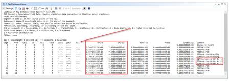
ZRD now includes data needed to accurately track rays in systems with reflective, refractive, and diffractive optics.
The Zemax Ray Database (ZRD) file generated when running an NSC ray trace has been improved to include new ray segment properties. It now includes total internal reflection (TIR) as a flag, optical path length (OPL) in lens units, OPL in wave units, and diffraction orders. These properties can be tracked and filtered using the new filters X_TIR, X_DIFF, and X_NDIF which filter for TIR events at a specific object or face, diffraction events at a particular object or face, and a total number of diffraction events, respectively. Also, the new filter X_GHOSTN returns rays that ghosted a specific number of times at a particular object or face.
1.2 PATH ANALYSIS IMPROVEMENTS (PREMIUM AND ENTERPRISE EDITIONS)
Leverage ZRD enhancements for increased insights and data usability in complex systems.
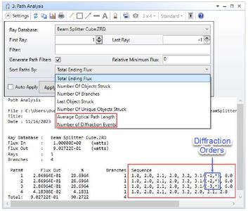
The path analysis tool uses the new ray data information in the ZRD to improve functionality. The tool constructs path sequences using objects’ faces and diffraction orders along the ray path. The path sequence includes object and face using the object.face notation and diffraction using the/(OrderX,OrderY) notation. Sequences containing different diffraction orders are considered separate paths even if they follow the same order of object faces. The new X_SEQ filter uses these path sequences to enable path filtering in filter-enabled analyses and ray trace tools. Additionally, the path sequences can now be sorted by two new options: Average Optical Path Length and Number of Diffraction Events.
1.3 EXPORT REDUCED ORDER MODEL TO SPEOS IMPROVEMENTS (ALL EDITIONS)
Added asymmetric system support with an improved reduced order model and 2D sensor sampling.
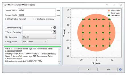
The Export to Speos Lens System tool was renamed and improved. The feature can now be found on the File tab under its new name "Export Reduced Order Model to Speos". The reduced order model (ROM) generated by this tool is now comprehensive and includes all the parameters needed for the Speos simulation. Therefore, the output settings are no longer required and have been removed. This tool now supports asymmetric lens files with the newly enabled 2D sensor and ray grid sampling. The 2D sensor sampling increases the accuracy for asymmetric systems as it accounts for the asymmetric field of view behavior. Radial sampling is more efficient for rotationally symmetric systems. The standardized ray grid sampling also improves speed and enables accurate ray data to be included in the ROM.
Please note that STAR data is not currently supported as a part of creating the ROM but this limitation
may be addressed in a future update.
1.4 EXPORT OPTICAL DESIGN TO SPEOS (ALL EDITIONS)
Export an optical system design to Speos to perform system-level stray light analysis.
The new Export Optical Design to Speos tool exports supported geometries and optical parameters from an OpticStudio lens design into a .odx file that can be directly imported into Ansys Speos. This tool enables a streamlined workflow between the component-level design and performance analysis in OpticStudio and a system-level stray light analysis in Speos.
To ensure high geometry fidelity between the OpticStudio and Speos models, the data imported into Speos retains all parametric information about the optical geometry. Sequential and Non-Sequential modes are supported with refractive standard and aspheric objects and surfaces. Material data and coating performance are also included.

Please note that after importing and generating the optical components in Speos, you should check the default meshing settings as they might need be adjusted if high optical accuracy is required.
1.5 PHASE SLOPE MAP AND PHASE SLOPE CONTROLLING OPERANDS (ALL EDITIONS)
Easily analyze and control the phase slope that diffractive and phase surfaces add and keep the diffractive optics manufacturable.
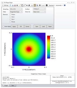
Two new phase slope analyses have been added to the Surface analysis group on the Analyze tab, for use with surfaces (and only surfaces) that add a phase change to the ray, such as diffraction gratings. With these new analyses you can evaluate the tangential, sagittal, x, or y phase slopes of the surface, allowing you to validate that the design of the underlying phase surface is manufacturable. These analyses enable the integration of meta-elements and other diffractive components designed using electromagnetic simulation tools like Ansys Lumerical RCWA into optical systems designed with OpticStudio.
The Phase Slope analysis displays the slope of a phase surface in 2D color and 3D surface Descriptions. It is compatible with decentered apertures and uses a uniform X-Y points grid to extract the phase slope value displayed.
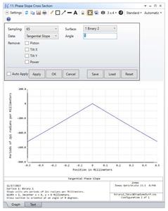
The Phase Slope Cross Section displays the phase slope at a specific angle across the full aperture of the surface. This tool calculates the surface phase as a cross-section across the full clear diameter or diameter of the surface.
Additionally, two new merit function operands constrain the phase slopes during optimization to keep phase slope values within manufacturable ranges. The PSLP operand returns a single phase slope value at a specified X-Y location on the surface. The direction of the slope and whether to remove the piston, tilts, or power before the calculation can be customized. The QSLP operand can return several phase slope parameters, such as phase slope RMS, P-V, minimum and maximum values. As well, it can return coordinates with the minimum or maximum phase slope or values removed from the phase data (i.e. when removing piston, tilt X/Y or power from the data).
1.6 SAG MAP IMPROVEMENTS (ALL EDITIONS)
Improved off-axis sag analysis with enhanced merit function operands to constrain sag for manufacturability.
The off-axis algorithm in the Surface Sag, Slope, and Curvature maps has been updated to provide faster and more reliable results while supporting more off-axis surface shapes. This tool can analyze a surface in a coordinate system tilted and decentered to the vertex of the off-axis part. Note that surfaces with vertex tilt terms, such as the Tilted surface type and Zernike Sag surfaces that use tilt terms Z2 and Z3 are not supported.
Surface sag and phase data can be retrieved and constrained for optimization using the Merit Function operands DSAG, DSLP, DCRV, DPHS, and PSLP that return sag or phase data at specific points. These operands now have a "Mode" setting so that the X and Y points specified can be either in lens units or in coordinates normalized to the aperture semi-diameter. Normalized coordinates are preferred for optimization because the size of the part may change. The SSAG, SSLP, SCRV, SPHS, and QSLP operands return data about the surface data set, such as P-V and RMS. Slope and Curvature data are directional, and for consistency, all related operands now contain an "Orientation" flag that allows the user to choose Tangential, Sagittal, X, or Y directions.
1.7 DIFFRACTIVE MODELLING: DLL FOR DIRECT MODELING OF METALENSES IN OPTICSTUDIO AND LUMERICAL (PREMIUM AND ENTERPRISE EDITIONS)
Simulate metalens components on a large scale.
A new DLL enables modelling of large-scale metalens components in OpticStudio. To use this DLL, users must first simulate and generate meta-atom data from Ansys Lumerical and then read the data into OpticStudio via this DLL. The input is either a pair of files with file extensions .pmap and .aph or a single file with extension file name .h5.
1.8 MECHANICAL DATA IN MATERIAL CATALOG (ALL EDITIONS)
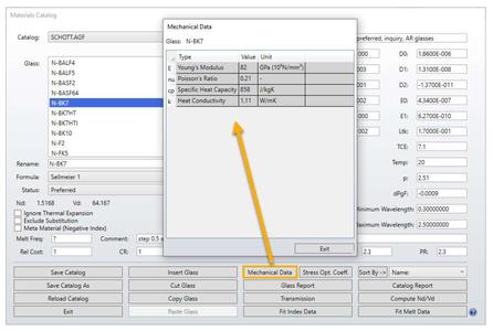
Added more material information to support Multiphysics workflows.
OpticStudio now features mechanical properties in the material catalog. Vendors now can provide information that could be pertinent to multiple steps in a cross-product multiphysics workflow, i.e. when your optical design is sent to your FEA (Ansys Mechanical) or CFD (Ansys Fluent) tool for analyzing the impacts of structural or thermal loads or environmental conditions on optical performance. This eliminates the need to search for these properties online and significantly streamlines the data exchange. The new available properties are:
– Young’s Modulus
– Poisson Ratio
– Specific Heat Capacity
– Heat Conductivity
– Stress Optical Coefficient
1.9 EXPORTING LAYOUT DescriptionS WITH THE ZOS-API (ALL EDITIONS)
Access the layout Descriptions using the API and use them for your customized analyses.
The API can now be used to retrieve static images of the Cross-Section, 3D Layout, and Shaded Model layouts. Layouts in sequential and non-sequential modes are supported, and settings, such as automatically setting camera viewpoints, resolution, configuration, and line thickness, are accessible via the API. The layout image can be saved by setting the SaveImageAsFile property to true and providing a filename to OutputFileName in the TheSystem.Tools.Layouts object.
Quick display is enabled by direct access to the R, G, and B image channels through the ImageExportData method of the TheSystem.Tools.Layouts object. This function does not need to save the image.
1.10 3D LAYOUT: DRAW PARAXIAL AND REAL ENTRANCE & EXIT PUPILS (ALL EDITIONS)
Analyze the shape and location of the pupils in your system.
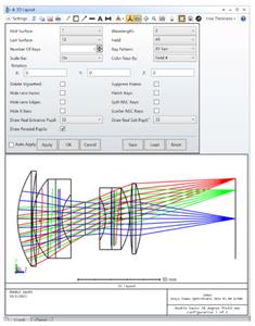
OpticStudio now features three new options added to the 3D Layout for showing the paraxial and real entrance & exit pupils. This feature enables users to study the shape and location of the pupils and analyze whether the system works as expected.
When checking "Draw Paraxial Pupils" in the settings of the 3D Layout Description, the paraxial entrance and exit pupils will be shown as black circles. When setting "Draw Real Entrance Pupil" or "Draw Real Entrance Pupil" to a number, the corresponding real pupils will be drawn as a polygon sampled by the selected number of points. The real pupils are drawn for each field. The color of these pupils follows the field settings.
1.11 RAY SEGMENTS DATA WHEN TRACING THROUGH GRADIENT BIREFRINGENT LENSES (ALL EDITIONS)
Analyze rays propagating through gradient birefringent lenses in greater detail.
A new setting was added to the Single Ray Trace analysis, called "Show Ray Segments".
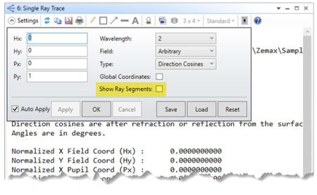
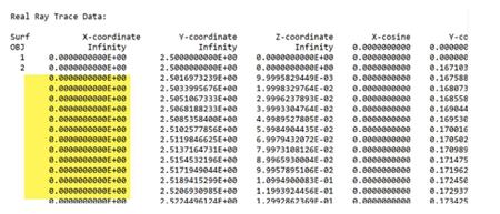
When this option is checked and the system has Birefringence In/Out surfaces where the Gradient Mode parameter is non-zero, the Single Ray Trace report will show the ray segment data inside of the birefringence.
–Diffraction Encircled Energy– Fixed an issue where incorrect reference coordinates were reported in Diffraction Encircled Energy if "Show Diffraction Limit" was not selected.
–Parasolid CAD files– Fixed an issue where rays were not included in exported CAD files when using the Parasolid libraries.
–Extended Diffraction Image Analysis– Fixed an issue for Extended Diffraction Image Analysis to improve results when paraxial and real image height calculations are significantly different.
–Extended Diffraction Image Analysis– Fixed an issue in Extended Diffraction Image Analysis where the vertical image direction was inverted.
–Exporting CAD files using Parasolid– Fixed a crash when exporting a CAD file using Parasolid when the system dimensions exceeded the maximum limits allowed by the Parasolid modelling kernel.
–User Defined Surface– Fixed an issue with the files us_polarization2.cpp and us_polarization2.dll to correctly pass back reflection and transmission values when method 0 is selected.
–Tolerance Operands– Fixed an issue where tolerance operands TRLX, TRLY, TRLR, TARX, TARY, and TARR could produce incorrect perturbation values of zero for non-axially symmetric systems.
–Convert to NSC Group– Fixed an issue where an off-axis mirror with a floating aperture was not correctly converted during a sequential to non-sequential conversion.
–Convert to NSC Group– Fixed an issue where a coating on a sequential mirror was applied to the wrong face after a sequential to non-sequential conversion
–Black Box– Fixed multiple issues where certain systems with Black Box surfaces would not successfully export a Speos reduced order model.
–Multiphysics Data Loader– Fixed a crash that could happen when loading STAR data for systems with Robust Ray Aiming turned on.
–Convert ZRD or ZBF to TSV– Fixed an issue with the Convert ZRD or ZBF to TSV tool where it would fail to generate an output file when the ZRD file is too large.
–SSAG MFE Operand– This fix enables calculation of the sag with no lateral limitations for cases where surface aperture is set to "None" or "Floating". Typically, SSAG returns zero outside of the surface aperture.
ANNOUNCEMENT
ZOS FILE FORMAT
.ZOS File Format will be retired in January 2025.
We are offering advanced notice of the .ZOS file format retirement. As of the 2024 R2 release (July 2024), OpticStudio will begin writing the same content type as found in the .ZMX file format to the .ZOS file format to begin the file type transition. The .ZMX file format will also replace the .ZOS file format as the default save option in Ansys Zemax OpticStudio. For some customers we are aware this decision may not support your existing workflow, which is why we are offering as much notice as possible. We encouraged users to begin converting existing files from .ZOS to .ZMX file format now. This change aligns with requests from long-term customers who have come to rely and depend on the product over decades and have chosen to have the .ZMX file as their format of choice. If you have any queries, please do not hesitate to contact your Account Manager.
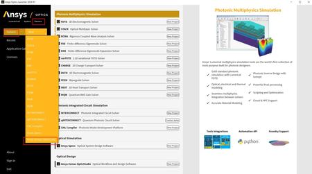
Ansys Optics solutionsoffer robust design, optimization, and verification simulation software backed by world-class support. These tools empower designers to expedite the development of groundbreaking optical products while improving performance, reliability, and yield. With a suite of top-tier physics solvers, Ansys Optics provides user-friendly workflows for precise multiscale system design, from the nano to macro scale, enabling the design of diverse applications across various industries.
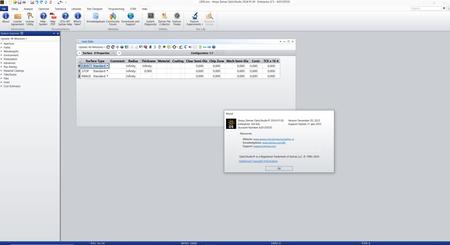
Ansys Zemax OpticStudio’sintuitive user interface includes easy-to-learn tools and wizards, which enable efficient simulation and design of any optical system. With more than 200 field points you can set up even the most complex freeform and non-rotationally symmetric systems. OpticStudio also includes a suite of optical engineering tools to analyze the performance of your system. In addition to the classic analysis functions, Zemax OpticStudio also offers Full-field Aberration analysis to improve freeform designs; contrast analysis for MTF optimization; and Image Simulation to produce photorealistic images of object scenes.
Zemax OpticStudio – Everything you need to design optical systems
Ansysis the global leader in engineering simulation. Through our strategy of Pervasive Engineering Simulation, we help the world’s most innovative companies deliver radically better products to their customers. By offering the best and broadest portfolio of engineering simulation software, we help them solve the most complex design challenges and create products limited only by imagination. Founded in 1970, Ansys is headquartered south of Pittsburgh, Pennsylvania, U.S.A. Visitwww.ansys.comfor more information.
In 2021,Ansys acquired Zemax, the world’s number one optical simulation toolset and Zemax is now "An Ansys Company." that is transitioning into the Ansys family. Initial connections between OpticStudio and Ansys Mechanical are already in place, and you will see further integration until it becomes part of the Ansys multiphysics capability.

peeplink.in/9af8e4e9fc38
NitroFlare
p3t91.SETUP.rar
Uploadgig
p3t91.SETUP.rar
Fikper
p3t91.SETUP.rar.html


Leave a Reply
You must be logged in to post a comment.